CIRCUIT CONFIGURATION
Components

Components are the fundamental building blocks of circuits, representing stateful operations on sparse sets or multisets.
See also: https://creatingintelligence.org/#circuits
List of all circuit components
| Component | Functionality |
|---|---|
input |
Gateway to the circuit’s function interface. Supports encoder plugins. |
output |
Gateway to the circuit’s function interface. Supports decoder plugins. |
circuit |
Embeds a circuit within a component. |
delay |
Delays incoming signals by one cycle. Integrates them temporally based on update rules. |
noise |
Generates pseudo-random sparse sets. |
auto |
Auto-associative memory component. |
associator |
Hetero-associative memory for supervised learning or state transition memory. |
predictor |
Hetero-associative memory for predictive learning. |
heteroencoder |
Hetero-associative memory for unsupervised learning and pattern separation. |
temporal |
Temporal-associative memory that maps temporal states to incoming inputs. |
Details and properties
- Data flow components, such as
delay, control the temporal integration of data over multiple timesteps. - Memory components, such as
autoortemporal, encapsulate a topological associative memory instance. - Excitatory signals are processed as positive integers, whereas inhibitory signals are processed as negative integers.
- Circuit components generally maintain a state across multiple execution cycles, whereas pathways are strictly stateless.
- The functionality of components can be extended via a standardized plugin mechanism.
- This framework supports the seamless integration of user-defined, custom components and plugins.
- Certain components may receive and send multiple signal partitions (block coding).
- Components are visualized as circles (data flow components) or squares (memory components) in circuit schematics.
| Property | Description |
|---|---|
send |
output slots, as a list of integers |
receive |
list of input slots or tagged pathways |
plugin |
extension module |
label |
user-defined vertex label in circuit schematics |
shape |
vertex shape (“square”, “circle”, or “none”) |
fill |
background color (palette index 0 to 15) |
size |
font size, given in points |
color |
font color (palette index 0 to 15) |
$comment |
notes for humans, ignored by the framework |
Sending and receiving data
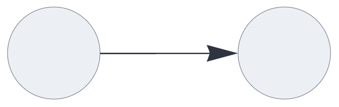
A pathway is defined via a slot number that occurs in one
component’s send parameters and in another (or the
same) component’s receive parameter. The choice of slot numbers
is arbitrary. The same slot can be received by multiple
components (multi-casting). However, the same slot number must
not occur in multiple send parameters.
{ "hyperparameters": {"default": [1000, 10]},
  "dataflow": [
    {"component": "input", "send": [1]},
    {"component": "output", "receive": [1]}
  ]}
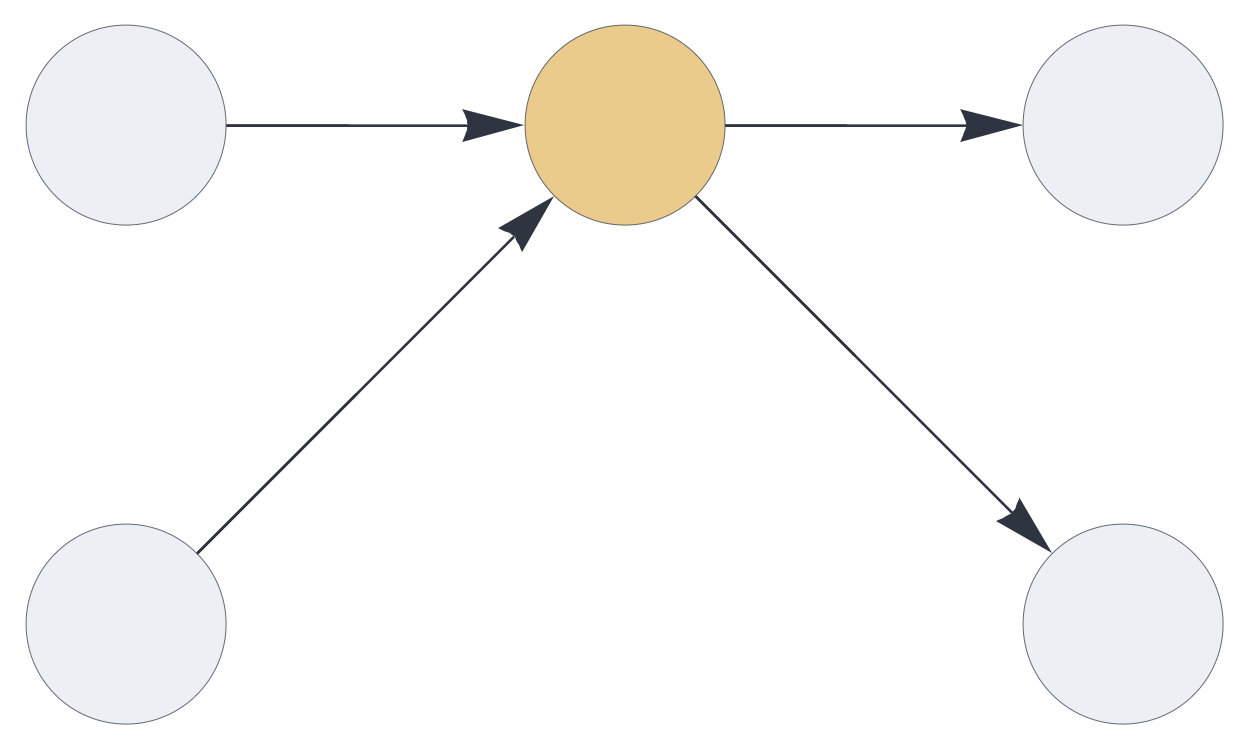
Lists of slot numbers denote disjoint blocks. Here the delay component receives and
sends two disjoint set partitions:
{ "hyperparameters": {"default": [1000, 10]},
  "dataflow": [
    {"component": "input", "send": [1]},
    {"component": "input", "send": [2]},
    {"component": "delay", "send": [11, 12], "receive": [1, 2]},
    {"component": "output", "receive": [11]},
    {"component": "output", "receive": [12]}
  ]}
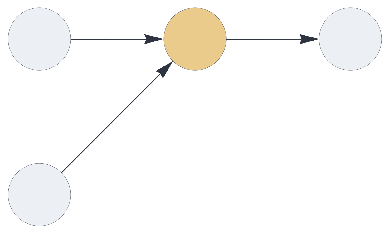
receive parameters wrapped in a list denotes
signal merging:
{ "hyperparameters": {"default": [1000, 10]},
  "dataflow": [
    {"component": "input", "send": [1]},
    {"component": "input", "send": [2]},
    {"component": "delay", "send": [11], "receive": [[1, 2]]},
    {"component": "output", "receive": [11]}
  ]}
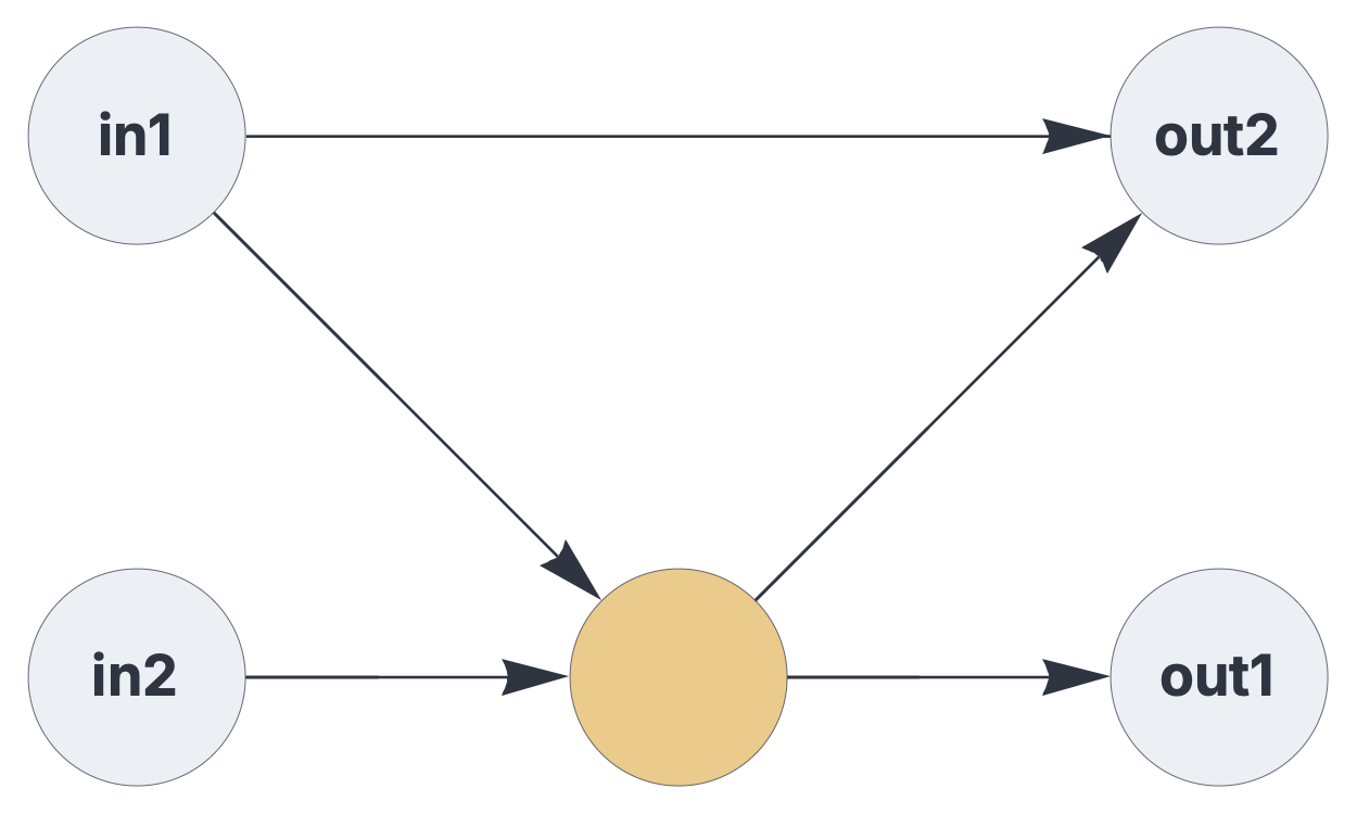
A circuit that combines pathway merging and block coding:
{ "hyperparameters": {"default": [1000, 10]},
  "dataflow": [
    {"component": "input", "send": [1], "label": "in1"},
    {"component": "input", "send": [2], "label": "in2"},
    {"component": "delay", "send": [11, 12], "receive": [1, 2]},
    {"component": "output", "receive": [11], "label": "out1"},
    {"component": "output", "receive": [[12, 1]], "label": "out2"}
  ]}
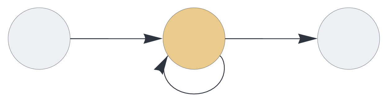
A simple feedback system, routing the component’s output slot directly back into its input:
{ "hyperparameters": {"default": [1000, 10]},
  "dataflow": [
    {"component": "input", "send": [1]},
    {"component": "delay", "send": [11], "receive": [[1,11]], "rate_limit": 1},
    {"component": "output", "receive": [11]}
  ]}
Encoders, decoders, and update rules
Plugins extend the functionality of base circuit components
while inheriting their properties and hyperparameters. Update
rule plugins govern state updates in auto, delay, and temporal components to
control temporal integration and associative behavior. The input and output components can be
extended with encoder and decoder plugins, respectively.
| Plugin Type | Implementations |
|---|---|
| Encoders & decoders | codec maps symbolic tokens to
random SHRs using a globally shared lexicon based on
auto-associative pattern matching. category encodes integers
0 to K-1 as non-overlapping SHRs. binning clusters similar
SDRs into categorized bins based on matching thresholds. |
| Vector encoders | vectorencoder
projects dense vectors into hyperdimensional space using sparse
binary matrices and kWTA. flyhash applies the classic
flyhash algorithm to achieve similar SDR mapping for real-valued
vectors. |
| Base update rules | replacement entirely
substitutes the previous state with new data, bypassing capacity
limits. augmentation computes
the multiset aggregation of signals, which converges
incrementally to a stable state equivalent to a deduplicated set
union. |
| Subtractive rules | residual removes the
retrieved pattern from the memory’s state to leave only novel
elements for anomaly detection. difference applies a
symmetric multiset difference to enable generative retrieval
behavior. complement
removes the current incoming signal from the state
entirely. |
| Filtering & sequence rules | coincidence retains
only matching elements between query and retrieved patterns. permutation replaces
the temporal state with its permutation before augmenting it
with current signals, thereby preserving sequence order in
temporal tracking. |
In the following example, the input component loads the codec plugin, the delay component is extended
via the augmentation update
rule plugin, and the output component uses the
same encoder/decoder as the input.
{ "hyperparameters": {"default": [1000, 10]},
  "dataflow": [
    {"component": "input", "plugin": "codec", "send": [1]},
    {"component": "delay", "plugin": "augmentation", "send": [11],
        "receive": [1], "capacity": 1},
    {"component": "output", "plugin": "codec", "receive": [11]}
  ]}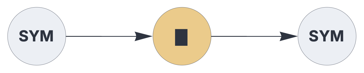
As shown in the example above, plugins typically modify the visual appearance of components in circuit schematics.
Component visualization
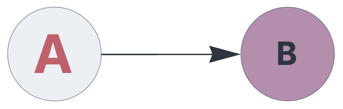
In circuit schematics, you can customize individual
components’ label, color,
fill, and size properties:
{ "hyperparameters": {"default": [1000, 10]},
  "dataflow": [
    {"component": "input", "send": [1],
        "label": "A", "color": 11, "size": 20},
    {"component": "output", "receive": [1],
        "label": "B", "fill": 15, "size": 12}
  ]}